Key Takeaway:
|
The battery management system, or BMS, is commonly characterized as a monitoring layer, a protection device, or a cell-balancing function. Within any installation, the battery constitutes the largest share of capital expenditure and the principal concentration of technical and safety risk. Whether that capital is recovered across a full service life or written down following accelerated degradation or a thermal event, is not determined by the cells alone. It is determined by the electronics that govern how those cells are measured, balanced, protected, and permitted to operate.
A component this consequential is rarely the one under discussion. The BMS is specified once, integrated, and thereafter assumed to work, which is precisely the condition under which its limitations surface only after the asset is in the field.
Within an energy storage system, the BMS is the layer that turns a stack of cells into a controllable, trustworthy asset. It sits between the cells and everything above them — the power conversion system, the energy management system, and the operator — and it carries four core responsibilities.
The battery management system continuously measures the state of the pack: individual cell voltages, pack current, and temperature at multiple points. This is the sensory layer everything else depends on. A single drifting cell, or a rising temperature reading at one node, is often the earliest sign of a developing problem — and those signals emerge gradually, as millivolt-level deviations that build over hours or days. What determines whether they are caught is not how often the system samples, but how finely it can resolve a reading and how consistently it does so across every channel in the pack. A measurement that cannot distinguish a real deviation from noise, or that varies from one cell to the next, provides no usable warning at all.
Raw measurements only become useful once they are interpreted. The BMS estimates State of Charge (SOC) — how much usable energy remains — and State of Health (SOH) — how much the cells have aged relative to their original capacity.
The accurate SOC keeps the pack from being over-used or under-used against its real limits.
The SOH tells you, and your dispatch strategy, how the asset is degrading over time and when it will need attention.
Cells in a series string never age at exactly the same rate. Left unmanaged, the weakest cell caps the usable capacity of the whole string and reaches its limits first. Balancing redistributes charge so cells stay closer together in voltage, improving consistency across the pack. The practical payoff is a longer working life for the asset, because no single cell is forced to carry the burden of the group.
Monitoring and estimation feed a set of protective actions. The battery management system guards against overcharge and over-discharge, against high and low temperature, and against overcurrent in both the charge and discharge directions. When a measured value crosses a defined threshold, the system intervenes — limiting current or opening the circuit — before the condition can damage cells or escalate into something worse.
The battery management system acts as the brain of the storage system, directing steady operation across the whole plant. The functions above only protect the asset for as long as that brain keeps working. If a safety-relevant function fails, the consequence is not limited to a single missed reading. In the worst case, the system loses the ability to protect itself, a fault escalates into loss of control, and the result is severe damage to the asset — and, potentially, risk to the people around it.
Failures rarely start large. A sensor drifts, a signal is delayed, a value is misread. On its own, each of these is minor. The danger is the chain that follows: an inaccurate temperature reading means a protection threshold is never triggered; an untriggered protection means an overcurrent or over-temperature condition simply continues; a continuing condition stresses cells toward thermal runaway. What began as a small component fault has become a functional failure of the safety function itself — the exact thing that was supposed to prevent the outcome.
"Safety" in this context covers two distinct ideas, and a capable BMS has to carry both, a dual barrier of functional safety and information security.
Functional safety is about the system behaving correctly when its own components fail, detecting the fault and moving to a safe state on its own. It is not a new idea invented for batteries; it grew out of machinery-safety practice in the 1970s and has since absorbed systems-safety theory, reliability engineering, and quality management into a complete engineering discipline. Its core work is the study of failure: analysing, systematically, how a product moves from a small fault to an error and finally to a full functional failure — then deploying measures that either prevent the failure or limit its consequences.
Information security, or cybersecurity, answers a different question entirely: it protects the system from external interference: unauthorised access, tampering, or manipulation of data and commands. One asks what happens when a part breaks; the other asks what happens when someone attacks. Treating either as a substitute for the other leaves a gap, which is why a serious battery management system is engineered to stand behind both.
Because failures propagate, safety cannot be bolted on after the core design is finished. A protection feature added late tends to cover the failure modes someone happened to think of, rather than the ones a systematic analysis would surface. Building safety in from the start — identifying failure modes first, then designing mechanisms specifically to catch them — is the difference between a system that usually works and one that behaves predictably even when parts of it do not.
At HiTHIUM, we take that principle literally. HiTHIUM’s in-house BMS is developed through a structured process that moves from safety analysis to requirement decomposition, mechanism design, and test verification. So, every safety measure is traceable to a specific goal rather than added on intuition.

We begin by defining what the system must never allow to happen. That produces seven safety goals: protection against overcharge, over-discharge, over-temperature, low-temperature, overcurrent, and discharge overcurrent, plus safe shutdown protection. Each goal is a concrete outcome the design is held accountable for, not a general aspiration.
With the goals set, we analyze the BMS at the function level, 14 functions in total, and identify every potential failure mode of each. Twelve of these functions are strongly safety-related, and for each one we design safety measures tailored to the specific ways it can fail, rather than applying a single generic safeguard across the board.
Each safety goal is then decomposed from the top down, translating a high-level objective into concrete, verifiable requirements at the component level. This process yields more than 240 component-level functional safety requirements — the layer where an abstract goal such as "prevent overcharge" becomes specific enough to design against and test.
From a pool of roughly 140 candidate mechanisms, we evaluate and select more than 90 for integration, favoring independent redundancy and additional check-and-handle logic so that no single fault can defeat a protection. Communication failure illustrates the approach. Data loss, a stuck signal, an unexpected change in a value, or messages arriving out of order are each countered by a matching mechanism — timeout monitoring, frame sequence-number checks, and redundant verification. So, a faulty link is detected and handled rather than silently trusted.
A safety mechanism is only credible once it has been shown to work. For each identified failure, we actively inject the fault and observe whether the system responds as intended — moving to its defined safe state. This is covered by 278 dedicated test cases: verification by demonstration, not by assumption.
This process is aligned with recognized international standards. IEC 61508 is the foundational functional-safety standard for electrical, electronic, and programmable electronic safety-related systems, defining the safety lifecycle and the integrity levels used to size risk reduction. ISO 13849 covers the safety-related parts of control systems, and IEC 60730 governs automatic electrical controls.
We do not stop at applying these standards internally. We invited a panel of senior functional-safety specialists to review our process, analysis, design, and testing end to end, and an independent third-party body then assessed the battery management system against each standard.
The outcome is a triple certification:
SIL 2 under IEC 61508,
Performance Level d (PL d) under ISO 13849
Class B under IEC 60730.
Building to these benchmarks — and having them verified externally — keeps the analysis, the mechanisms, and the testing accountable to an outside standard rather than an internal opinion. We treat the certificates as a responsibility rather than an endpoint: field feedback keeps coming in, and the product keeps being refined against it.
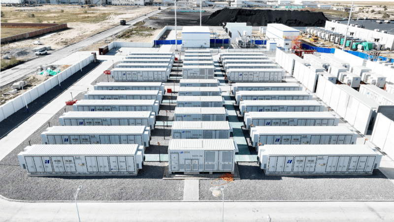
A battery only holds its value if the system behind it is engineered to defend that value every day it runs — which is the standard we hold our in-house BMS to at HiTHIUM. Built from systematic failure analysis and independently certified against recognised international standards, it lets you treat your battery not as a liability to be managed, but as an asset you can depend on across its full-service life.
Contact HiTHIUM today to get more information about BMS!
[1] Intertek — IEC 61508: The Functional Safety Standard. https://www.intertek.com/etl/standards/iec-61508/
[2] Microcontroller Tips — What's the difference between IEC 61508, 61511, ISO 26262 and 13849 functional safety standards? https://www.microcontrollertips.com/whats-the-difference-between-iec-61508-and-61511-and-iso-26262-and-13849-functional-safety-standards/
[3] IAR — Safety-certified tools make the difference (overview of IEC 60730 and related standards). https://www.iar.com/knowledge/learn/safety-certified-tools-make-the-difference




 Previous: